)
) )
)DIMMING
Analog Control (1–10 V)
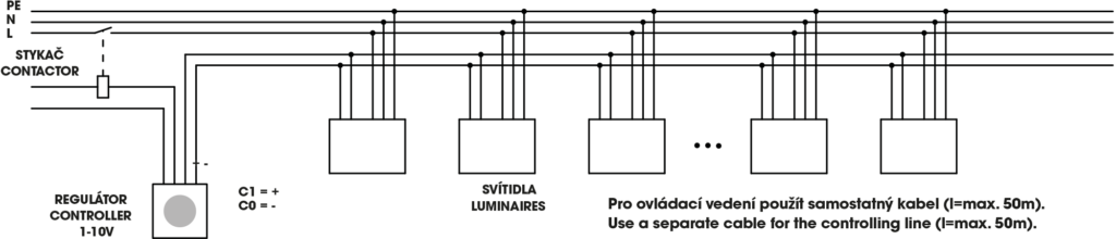
Analog control is the oldest and simplest type of regulation. It is mainly used for small systems together with a manual regulator or a daylight sensor for automatic regulation.
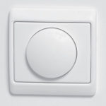
Manual regulator (1–10V)
Basic dimming circuit diagram - analog (1–10 V)

Dimming circuit diagram with contactor - analog (1–10 V)
Daylight sensor
Necessary to specify whether for T5 or T8
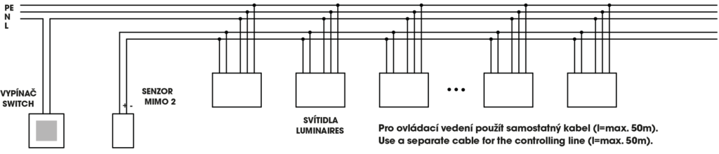
MIMO 2 sensor (1-10V). Automatic regulation which preserves a constant lighting level that can be adjusted from c.200 to 600 lx. It can regulate up to 15 ballasts (luminaires)
Dimming circuit diagram - MIMO2 (1–10 V)
DALI - Digital Control
The DALI digital control is the a state-of-the-art type of regulation and control used in modern installations for integration of a system into intelligent building control.
(Digital Addressable Lighting Interface) offers new possibilities. The DALI is defined as a “Master-Slave” system where control modules communicate with each other, send commands to luminaires that receive them. The whole system is conceived for 64 components that can be represented not only luminaires, but also relay modules used for switching on/off something. These 64 components can be divided in up to 16 groups where the components do not have to be just in one group. It is also possible to set up to 16 scenes.
The luminaires are connected with a paired cable and all the setting is done only after the installation of the luminaires. It is therefore possible to change the arrangement of groups of luminaires any time afterwards. It also is possible the change the way of switching on from separate rows to separate “columns” or to control one luminaire separately and the rest separately. All of this can be done without changing the wiring system.
Control modules can be very simple – you can imagine a common button used for switching on / off a group of luminaires or creating a “scene”. A “scene” is a setting that has been saved to the memory and to which you can come back at any time.
You can create various scenes such as: a scene for common operation, a scene with dimmed light used for presentations or a scene with reference lighting only for the security guard.
A control module can also control a lighting system according to daylight or work as a receiver of a wireless controller.
The DALI system allows you to enter the system and change the configuration according to the current requirements. The DALI system can also be integrated into other systems such as EIB, LonWorks, and the like.
If you are interested in using DALI, we are ready to help you with a concrete application. Do not hesitate to contact us.
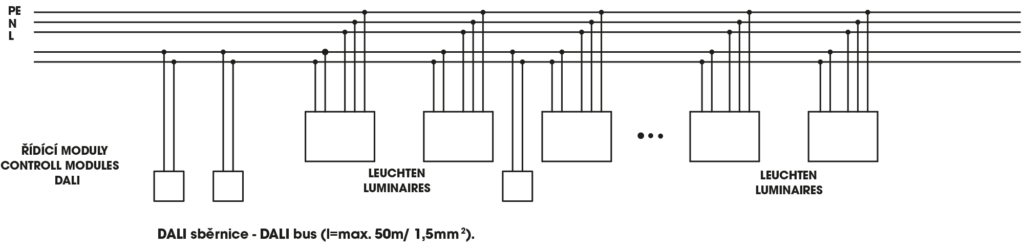
Basic dimming circuit diagram – DALI
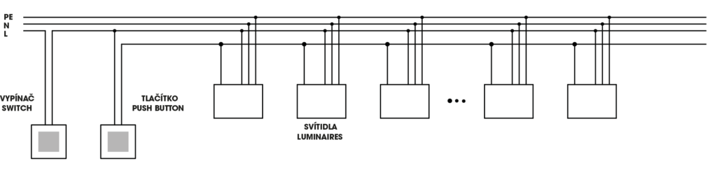
Touch DIMM
It is also possible to control a lighting system with a button.
Some dimmable ballasts can be controlled with a button. The control is done in the following way: You can switch the light on/off by pushing the button for a short time. By pushing the button for a longer time, you can increase or reduce light.
The number of ballasts to control this way is theoreti- cally unlimited although a maximum of 20 ballasts is recom- mended in practice.
This type of regulation is suitable for controlling from sev- eral places (buttons connected in parallel). This type of regu- lation is offered with HELVAR ballasts and TRIDONIC ballasts.
Characteristics of „sc“ HELVAR ballast:
Control is done with neutral, but it is also possible to use the phase. The ballast does not have a memory which means that after being switched on, the luminaire always switches on 100%. Attention – the luminaires will switch on by themselves after a power failure even if they have been switched off with a button only. This can be avoided by adding a switch. An a non-synchronous situation can happen rarely (some luminaires are switched on and some switched off). You can synchronize the luminaires by switch- ing off the circuit-breaker.
Characteristics of „ECO and EXCEL“TRIDONIC ballasts :
Control is done with the phase. The ballast has a memory which means that, after a power failure, the luminaire reaches the same level of light as before the power failure. After a power failure, the luminaires get back to the condition they were in before the power failure. An a non-synchronous situation can happen rarely (some lumi- naires are switched on and some switched off). You can synchronize the luminaires by pressing the button for more then 10sec (all the luminaires will switch on 100%).